|
|
|||||||||||||||||||||||||||||||||||||||||||||||||||||||||||||||||||||||
the authors
|
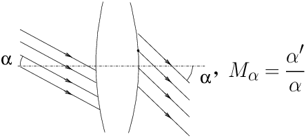
Glossary of technical terms in photographic opticsby Emmanuel BIGLER (1) et Yves COLOMBE 1 E. Bigler's e-mail Abstract: Contents1 aberrations 2 afocal (system) 3 angular magnification 4 camera (field) 5 camera (folding) 6 camera (reflex) 7 camera (view) 8 cardinal elements 9 centred optical systems 10 close-up 11 conjugate (paraxial equations) 12 convergence ratio 13 diaphragm 14 dioptre 15 distance (algebraic) 16 distortion 17 f-stop (diaphragm) 18 field camera 19 focal length 20 focal planes 21 object focal point 22 image focal point 23 flange focal distance 24 back focal distance 25 formulae (Descartes, Newton) 26 Gaussian optics 27 geometrical image 28 image space 29 layout (optical system) 30 longitudinal magnification 31 macrophoto 32 magnification (angular) 33 magnification (longitudinal) 34 magnification (pupil) 35 magnification (transverse) 36 meniscus (simple lens) 37 monorail view camera 38 negative optical system 39 nodal planes 40 nodal points 41 inter-nodal distance 42 object / image - real / virtual 43 object space 44 optical axis 45 optical centre 46 optical system 47 paraxial approximation 48 positive optical system 49 principal planes 50 principal points 51 pupils 52 pupil magnification 53 real / virtual image 54 reflex camera 55 refracting power 56 refracting surface 57 refractive index 58 retro-focus lens 59 separation (principal points) 60 tele-converter 61 telephoto lens 62 transverse magnification 1 aberrationsIn instrumental optics, the word aberrations denotes the real behaviour of light rays in an optical system (46), which actually differs from what could be derived from the approximate model of Gaussian optics (26), for light rays far from the optical axis (44), i.e. non-paraxial rays (47). See: ref. [1] for more details. French: aberrations - German: Abbildungsfehler, Aberrations. 2 afocal (system)The main property of an afocal system is: an incoming beam of parallel rays, inclined at an α angle with respect to the optical axis (44), exits in the form of a beam of parallel rays inclined at an α′ angle (fig. 1). This property allows to define the angular magnification (3) Mα of the afocal instrument (eq.(1)):
It is not possible to focus an image of a distant object on a film or sensor with such a system, which is why all photographic lenses have a nominal focal length (19). A telescope or ground telescope, or one of the two monocular elements in a pair of binoculars, is an afocal system when set to the standard position infinity → infinity. In practice, most visual instruments focus the image at a distance of about one metre forwards, so they are a slightly negative system (38). Do not confuse an afocal system used in front of the lens as a teleside converter (see ref.[2]), with a tele-converter (60) for reflex cameras (54) with interchangeable lenses. See also: ref. [3]. French: système afocal - German: Afokales Linsensystem. 3 angular magnificationThe angular magnification Mα for an afocal (2) visual instrument (see figure 1) is defined by tracing a beam of parallel rays that intersect the optical axis at the input at an angle α with respect to the axis; at the output the rays are parallel and intersect the axis at an angle α′. The angular magnification Mα is equal to the ratio of the angles α′ / α. Mα being a ratio of angles, we can define these angles in any unit we want, in radians or in degrees as long as both α and α′ are expressed in the same unit. For an instrument such as a magnifying glass or a microscope where objects are located at a finite distance, the commercial intrinsic magnification Mic is defined as the ratio between the angle at which the object is seen through the instrument and the angle at which the object is seen with the naked eye at the conventional distance of 250 mm. A magnifying glass that magnifies 10 times makes a millimetre scale seen through the magnifying glass appear to be the same as a centimetre scale seen with the naked eye at 250 mm. The relationship between Mic and the focal length f of a magnifying glass is : Mic = 250/f(in mm). A 5x magnifying glass has a focal length of 50 mm, a magnifying glass with a focal length of 100 mm “magnifies” 2.5 times. 4 camera (field)See: field camera (18). 5 camera (folding)See: field camera (18). 6 camera (reflex)See: reflex camera (54). 7 camera (view)See: monorail view camera (37). 8 cardinal elementsThe cardinal elements of a thick optical system are the focal
points (22, 21), the principal points and
planes (49, 50), the nodal
points and planes (39, 40).
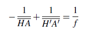
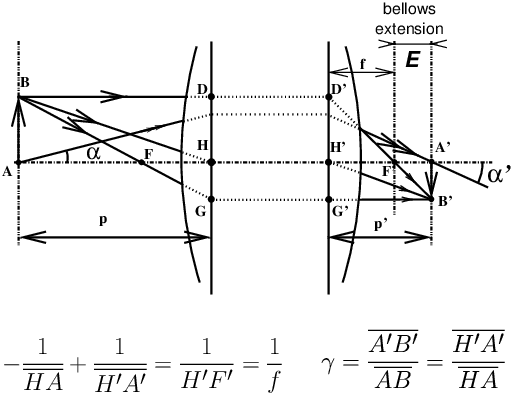
See ref. [18]. 9 centred optical systemsA combination of flat, spherical or aspherical refracting or reflecting surfaces, thin or thick lens elements which are rotationally symmetrical about the same optical axis (44) (see refs. [5] and [18]). The properties of these systems can be fairly easily extended to a combination of centred systems coupled together by mirrors insofar as the reflections make the axes of different subsystems correspond to each other. For example, the pentaprism viewfinder system of a reflex camera (54) combined with the imaging optics, the reflex mirror and the eyepiece behaves almost like a single centred system, the only difference being a simple image shift. The centred system model makes possible to explain almost all image formation in photographic systems. Exceptions are special optics such as cinema anamorphic lenses, which consist of an assembly of centred systems, prisms and cylindrical lens elements. 10 close-upShooting conditions for which the transverse magnification (11) G is between 0.1 and 1. 11 conjugate (paraxial equations)Knowing the focal length (19) f of a thick optical system and the position of the focal points F, F′ and of the principal planes H, H′, the position of the images in relation to the objects is determined either by Descartes’ formula (with origins at the principal planes) or by Newton’s formula (origins at the focal points). If A and A′ are two conjugate points on the axis, the following algebraic formulae are available:
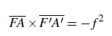
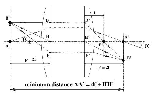
The total distance A A′ between the object and the image is given in a general algebraic way by equation (6):
In the case of a photographic lens with a positive focal length f, with a real object and a real image, we have γ < 1; if we define M = |γ|, equation (6) yields:
Link between the absolute value of the transverse magnification M and distances A H and H′ A′:
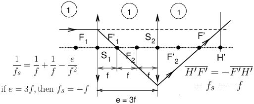
Note that in equation (7), the principal planes separation H H′ (59) can have a positive or negative value, even for a positive optical system (48). The smallest object-image distance is obtained in the symmetrical object-image position “2f-2f” (figure 3); under these conditions : γ=−1 ; G=1 ; A H = 2f ; H′ A′ = 2f ; A B = − A′ B′.
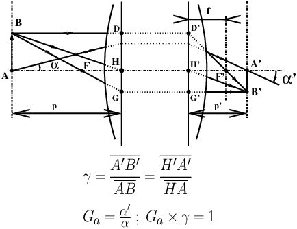
12 convergence ratioThe convergence ratio (see figure 4) Ga is the ratio of angles Ga = α′/α formed by rays intersecting the axis at an object A (angle α) and its image A′ (angle α′). If the object and the image are in the same transparent medium, we have the relation between Ga and the transverse magnification γ (11) :
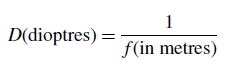
Equation (9) is a consequence of Lagrange-Helmholtz invariant (see refs. [5] and [21]), a fundamental property of spherical refracting surfaces, in the case of identical input / output media. 13 diaphragmSee: f-stop (diaphragm) (17) 14 dioptreUnit of measurement for the refracting power of a lens, defined as the inverse value of the focal length (19); dioptre value D is defined as
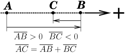
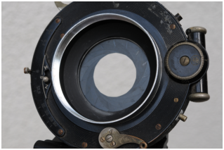
A photographic lens (positive optical system (48)) with a focal length (19) of 100 millimetres has a +10 dioptre value. A negative ophthalmic lens of -4 dioptres to correct myopia has a focal length of -250 mm. When a photographic viewfinder is said to be “set to -1 dioptre” it means that the image given by the viewfinder is focused at a distance of 1 m in front of the viewfinder. 15 distance (algebraic)On an axis oriented positively from left to right (figure 5), the algebraic distance AB is positive if B is to the right of A; we have: AB = − BA. We have the following one-dimensional version of the relation of addition and subtraction of vectors (ref. [15]), named segment addition postulate (ref. [16])
In most of classical optics textbooks, light travels from left to right; object space is on the left, image space is on the right. Beware, this convention is not universal, on some sectional views of lenses illustrating the technical documentation published by lens manufacturers, it is common to see the drawing presented with the reverse convention, that is to say with the image on the left and the object on the right. For the vertical axes, the axis is positively oriented upwards, which allows to define an algebraic value for transverse and angular magnification. In current photographic applications, the image is real (it can be detected on a film or on a sensor) and the magnification is always negative (the image is reversed). 16 distortionOptical distortion is a distortion of the image, which occurs when moving
away from the optical axis (44), when the object plane, the
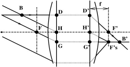
lens board and image planes are parallel. In this situation,
Gaussian optics (26) predicts that the image of an
object which is a square mesh grid is a homothetic square mesh grid of the
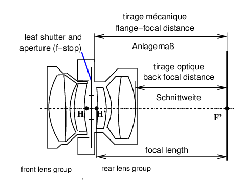
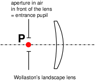
object (figure 6). See also ref. [17]. 17 f-stop (diaphragm)Aperture (ref. [13]) limiting the light beams that pass through a lens. In very old lenses, waterhouse stops (ref. [14]) were used, that is to say a plate drilled with a circular hole that was slid between the lenses. Most of modern lenses equipped with an adjustable aperture diaphragm use the principle of the adjustable iris diaphragm (figure 7). It is common for the aperture stop to be placed between the lens groups of a photographic lens, however in the case of Wollaston’s meniscus (36) lens (figure 14), a very old type of lens formed by a single convex-concave meniscus-shaped lens, the diaphragm is placed in the air, in front of the lens. Depending on where the aperture stop is placed, this opening always centered on the optical axis (but not necessarily circular), can act as either a field stop (limiting the visible diameter of the object space) or aperture stop (limiting the brightness of the image). In a well-designed lens, the aperture stop control ring is only used to adjust the brightness of the image, a correct location of the aperture aperture stop should not, in principle, limit the field. A correct setting of the aperture stop is a very important point in the
calculation of a high-performance lens, because where the aperture stop is
located has a great influence on aberrations (1) and
distortion (16). 18 field cameraField camera, flatbed view camera, folding view camera: Lightweight, sometimes folding, often made of wood, especially in formats
larger than 4x5 inches, heiress of the first photo cameras. Some field
cameras allow the lens board to be folded behind a front flap which makes
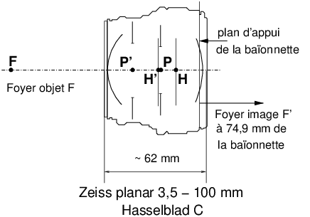
the camera easily transportable in the field. 19 focal lengthAlgebraic distance (15) noted in the general case f′,
defined by f′ = H′F′ which separates the principal image plane H′
from the focal point F′ (see figure 8). In the air we
have H′F′ = −HF for all systems. To simplify the
writing, we will call f this focal length H′F′ which is
positive for all photographic lenses. 20 focal planesPlanes perpendicular to the optical axis and which contain one or the other of the foci F and F′ of the system, at least if we are not dealing with an afocal (2) system. A beam of rays emitted by a Fs point of the off-axis object focal plane exits in object space (28) as an inclined parallel beam. A beam of rays entering the system parallel to each other but inclined with respect to the optical axis axis emerges at a point Fs′ in the image focal plane; Fs′ is sometimes referred to as a secondary focal point (see figure 8). 21 object focal pointPoint on the optical axis for which all the rays passing through this point in object space exit parallel to the axis in image space. (figure 8). It is noted : F. 22 image focal pointThe point on the optical axis where a beam of rays parallel to the axis is
imaged. Any ray entering the lens parallel to the axis exits at the
image focal point. It is noted : F′ (see figure 8). Warning: the image focal point is not the geometrical image of the object focal point! The image of the object focal point is at infinity on the axis under the form of a beam of rays emerging parallel to the axis. 23 flange focal distanceAs an intrinsic specification of a lens, it is the distance between the image focal point F′ (22) of the lens and a mechanical reference element on the lens; either the support plane of the lens board or a reference plane for the rear optical group (view camera lens, see figure 9); or the reference plane of the bayonet mount (reflex cameras (54) - see figures 11 and 22). What is intrinsic to the lens is the mechanical flange focal distance specification when focusing in infinity → focus setting. In the general case, the flange-to-image distance will be the distance
between the mechanical reference element and the image. Between the
infinity→ focus setting and the position “2f-2f” (figure
3), the flange-to-image distance must increase by one
focal length.
24 back focal distanceAs an intrinsic specification of a lens, it is the distance from the the last lens vertex to the image focal point F′ (22), see figure 9. In a single-lens reflex camera (54) with a flipping mirror, the rear lens element must not interfere with the movement of the mirror. Solutions usually implemented (sometimes simultaneously) are :
A retro-focus (58) lens has a back focal distance
in infinity→ focus setting longer than its focal
length (19); see figure 22. In the general
case, the back “glass-to-image” distance will be the distance from
the rear lens vertex to the image. Exactly like for the flange focal
distance, between the infinite → focus setting and
the “2f-2f” position (figure 22), the
“glass-to-image” distance must increase by one focal length. It is
possible to use on a SLR camera, lenses with insufficient back focal
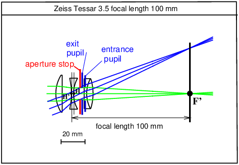
distance at infinity, provided that they are used only in
close-up (10) or
macrophoto (31) with a distance H′A′ (figure
2) much longer than the
focal distance (19). 25 formulae (Descartes, Newton)See : conjugate (paraxial equations) (11). 26 Gaussian opticsA theory of centred optical systems (9) which brings together in a few formulae and ray tracing rules all that is necessary for the construction of the position and size of images (see ref. [4]). Initially, the model only applies to slightly inclined rays that pass very close to the optical axis (44), but all centred systems, however complex they may be, behave in a similar way for these rays, called paraxial rays (47). For real photographic optics, the Gaussian approximation can be very helpful in modern lenses, well corrected for aberrations (1) and distortion (16), and allows the position and size of the images to be found correctly by extrapolating the symbolic Gaussian ray tracing non-paraxial rays. Exception in photography: ultra-wide angle fish-eye type lenses covering 180 degrees and more, where the rules of image construction are particular. French: approximation de Gauss - German: Gaußsche Optik. 27 geometrical imageThe locus in image space where the rays from different source points of the object that have been able to pass completely through the lens intersect. In the Gauss approximation (26), all rays coming from a single point in object space intersect at the same point in image space which, is called a geometrical image. Modern optical systems, very well-corrected of aberrations (1) realise this property very noticeably even for wide-angle lenses or large objects, so that in a real thick optical system, the formulae of Gauss approximation (26) can be used to determine the position and size of the images. 28 image spaceTransparent medium where the light that has passed through the lens is received and focused to make an image. In this medium the rays also propagate in a straight line. Each point in the object space is associated with a point in the image space by the conjugate formulae (11). Any symbolic ray tracing is not limited to images placed behind the lens,
one can also have virtual images (42) placed in front of
the lens, which, in the sense of conjugate
formulae (11), are “optically” located in the image
space. 29 layout (optical system)Layout of an optical system: symbolic geometrical tracing placing, for a centred system, the focal points, the principal and nodal planes; for a photographic lens in the air, the focal points, the principal planes, the first and last lens vertices, the position of mechanical supports (lens board, reference planes for screw or bayonet mounts) and the pupils. The technical data sheets of some manufacturers give the positions of the cardinal elements as well as the pupils and their diameters; it is also possible to find these values and redraw the layout of a lens from the patent data. See examples of such a drawing in figure 10,
figure 11 and figure 22.
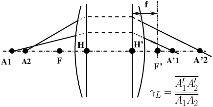
30 longitudinal magnificationLet A1A2 be a small segment (|A1 A2| ≪ |H A1|) of the optical axis bearing two source points A1 and A2. Let A′1 and A′2 be their images (figure 12). The longitudinal magnification γL is defined by:
Link between the longitudinal magnification γL and the transverse magnification γ (11):
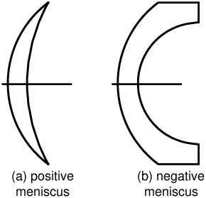
In general, the image of a volume element by a centred system is compressed (if |γ| < 1) or expanded (if |γ| > 1) in the longitudinal direction. The exception is the case where |γ| = 1; this is the case of the symmetrical object-image position “2f-2f” where γ = −1; in these conditions we have |γ| = |γL| = 1 and the volume image of a small object is, in the three dimensions of space, perfectly identical to the object, at scale 1. 31 macrophotoShort for: macro-photography, shooting conditions for which the transverse magnification (11) G is around 1, or greater than 1. 32 magnification (angular)See: angular magnification (3) 33 magnification (longitudinal)See: longitudinal magnification (30) 34 magnification (pupil)See: pupil magnification (52) 35��������������������������� magnification (transverse)See: transverse magnification (11, equation (4), figure 2). 36 meniscus (simple lens)A meniscus lens is formed by a bulging (convex) side and a hollow (concave) side (figure 13). If the radius of curvature of the convex side is smaller than that of the concave side (figure 13a), the lens is positive; if the reverse is true (figure 13b), the meniscus is negative. Meniscus lenses are used in many photographic lenses as well as ophthalmic glasses. Historically, one of the first lenses used in photography was a simple meniscus lens and a diaphragm named Wollaston’s landscape lens (1804) (figure 14, see ref. [26]). 37 monorail view cameraTechnical camera, view camera, based on the fixation of main elements on a single optical bench allowing focusing by moving along the rail as well as the rapid exchange of accessories. Monorail cameras, especially those used in studios, are usually made of metal. Compared to field cameras, their possibilities of rail extensions and movements, as well as their range of accessories are much more extensive, often at the expense of weight and compactness. French: chambre monorail - German: Optische-Bank Fachkamera (Großformatkamera). 38 negative optical systemAn optical system for which the focal length (19) H′F′ is negative as in a negative lens. By associating several positive lenses with well chosen distances between them, one can nevertheless obtain a negative system (see figure 15 and ref. [2]). The association of negative lenses, on the other hand, does not allow to obtain a positive system. French: système optique divergent - German: Negativ Linsensystem.
39 nodal planesA pair of conjugate planes located perpendicular to the optical axis and passing through the corresponding nodal points (40). For a photographic optics used in air, nodal planes are identical to principal planes (49). 40 nodal pointsA pair of conjugate points, N and N′ on the optical axis for which the convergence ratio (12) Ga (figure 4) is equal to +1, i.e. any ray passing through N at the input comes out by intersecting the optical axis at N′, being parallel to the input ray. For photographic optics used in air, the nodal points are identical to the principal points (49), N=H ; N′ = H′. An important property of the N′=H′ image nodal point is that a
small rotation of the lens around N′ hardly moves the image of a
distant object that would focus on a fixed screen placed near the focal
plane. It is assumed here that the objects being imaged are located very
far from the camera, a classic case in panoramic landscape photography.
This property of stationarity of the image is used in rotating
drum panoramic cameras in which the film is fixed in relation to the
landscape (or remains fixed by retrograde scrolling of film in synchronism with the
rotation of the entire camera) and the optics rotates in relation to the
landscape to accumulate a succession of thin strips reconstituting the
panorama. The object nodal point N plays a similar role if the lens is
reversed, but this is not used in practice. 41 inter-nodal distanceSee: separation (principal points) (59). 42 object / image - real / virtualObject and image must be understood in the context of geometrical optics, such as:
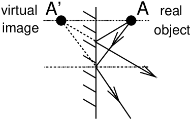
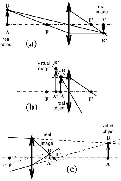
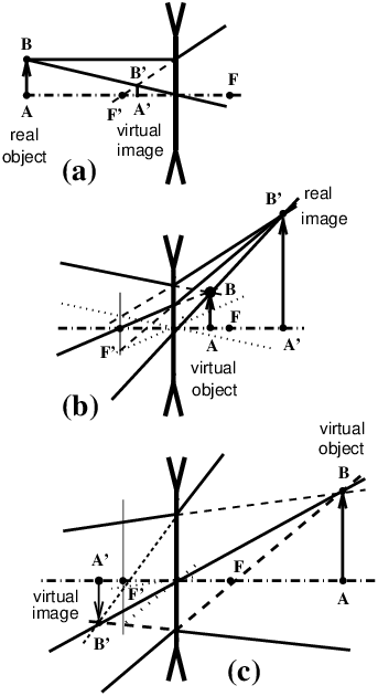
In fact, general conjugate formulae (11) given by equations (2) and (3) do not impose that the object is in front of the lens, or that the image is behind! If the object is in front of the lens, and that it is an “ordinary” object, of the real world, emitting or diffusing light, then for geometrical optics it is a real object and it is hard to see how it could be placed behind the lens, except to make the lens work reversed! In reality, and as astonishing as it may seem, geometrical optics allows the case where the object would be located behind the lens! This is what happens when another optical system is set to focus the rays behind the lens. The lens thus intercepts rays focused by the optical system in front of it, and it can sometimes give a real image of it, as if this object were real! In this situation of the object placed “behind the lens”, the object is a “virtual object”. In the same way, the photographic image that is focused on a camera ground glass, film or sensor is a real image, a detector can be placed where this image is focused. But there are also virtual images, the simplest example is the image given by a plane mirror (figure 16), you can see it every day in your bathroom! Rays reflected by a plane mirror seem to come from a world behind the mirror, symmetrically from the real world. It is not possible to place a detector where this image is “focused”, so it is called a virtual image, but it is seen in the same way as if a symmetrical real world were placed behind a window with the dimensions of the frame of the plane mirror. But one can easily take a picture of this virtual image and transform it into a real image. Figures below (figures 17 and 18) summarize what happens with a simple thin positive or negative lens. In order for the (virtual) object to be located behind the lens, the rays must be focused behind the lens with another optical system placed in front. In the case of a thick system, ray tracings on figures 17 and 18 remain valid, just shift the object space and the image space by a distance equal to principal planes separation (59) H H′.
43 object spaceTransparent medium in which the light eventually captured by the camera is emitted as an input to make an image. In this supposedly homogeneous medium, the rays propagate in a straight line. If the medium is not homogeneous (if the refractive index varies along the path of the rays) the rays can propagate along curved paths; this curvature explains the origin of the corrections to be applied to the apparent angular height of stars measured with a sextant pointig close to the horizon level, as well as the mirage phenomenon. Any symbolic ray tracing is not limited to sources placed in front of the
lens, one can also have virtual objects (42) placed behind
the lens, which, in the sense of conjugate
formulae (11), are “optically” located in object
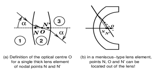
space. 44 optical axisThe optical axis of a centred system (9) is a straight line on which all the centres of all spherical refracting surfaces (56) of the system must be aligned. This axis is therefore the axis of rotational symmetry common to all spherical refracting surfaces constituting the system. Actually, refractive surfaces can be aspherical. In general, when talking about aspherical surfaces in photographic lenses, it is implied that these surfaces have an axis of rotational symmetry which is the same as the optical axis. This is not always the case: for example, in cinema anamorphic cameras, there are cylindrical lens elements and prisms; a cinema anamorphic camera combines centred systems and systems without an axis of rotational symmetry. The analysis of aspherical refracting surfaces, even with rotational symmetry, goes beyond the conditions of Gaussian optics (26). A rotation of an optical system centred around its optical axis, which is an axis of rotational symmetry of the system, produces no change in the image. French: axe optique - German: Optische Achse. 45 optical centreThe optical centre is only defined for a simple thick
lens (ref. [6]). Consider a thick simple lens with nodal points (40) N and N′. An incident ray coming from medium (1) points towards N on the optical axis (44) and refracts on the first surface (1-2) passing through O which is the image of N in medium (2). Point O is not necessarily inside the lens, if it meniscus shaped (36) (figure 19b). The ray then refracts through the second surface (2-3) and seems to come from N′, which is the image of N given in medium (3) by the two surfaces (1-2) and (2-3) forming the simple lens. The property of the nodal points (40) is that the angle of inclination α for any ray passing through N and N′ is the same at the entrance and exit. The term “optical centre of a thick compound lens” is sometimes read on the Internet. This notion is meaningless. In a complex optical system formed by the assembly of several lens elements, one can of course construct successive images of the object nodal point (40) N by progressing through all refractive surfaces (14) of the system; the last image being the image nodal point N′ given by the last surface. There are as many intermediate images of the object nodal point N as there are refractive surfaces (56) (minus 1). All these images are located on the optical axis (44), they are sometimes real, sometimes virtual (42), but do not play any particular role in photography. If one of these images is real, and is located in air (but not necessarily inside the lens), then at this point – if it is well chosen to limit only the brightness and not the field – the aperture diaphragm (f-stop) (17) can be placed so that the pupils (51), i.e. the images of the diaphragm (f-stop) given by the front and rear groups, will be placed in the principal planes. This arrangement, with pupils placed in the principal planes (49), is achieved, for example, in perfectly symmetrical lenses where the diaphragm (f-stop) is placed in the centre of symmetry. In conclusion, this insistence to absolutely want to try and find an “optical centre” inside a thick compound lens, comes from the omnipresence of the model of the thin positive lens element with a diaphragm at its centre, as well as the pinhole camera, to explain the formation of photographic images. Most of the time, the meaningless expression “optical centre of a thick compound lens” is used without justification:
It is indeed around the entrance pupil of the lens that the camera as a whole must be rotated, lens + detector, to make panoramas by image stitching avoiding the problems of impossible image stitching due to the change of point of view following the displacement of the entrance pupil (51, see refs. [11] & [12]). Now in all multi-lens photographic lenses built since the 19th century, entrance pupil, centre of symmetry (for symmetrical designs) or midpoint of the NN′ segment, and image nodal point are distinct! The entrance pupil is the point that defines the centre of projection or the centre of perspective for image formation. Of course, in a thin simple lens with a diaphragm (f-stop) in its centre, the nodal points and the entrance pupil are merged in the centre of the thin lens. But this is not the case in a thick compound optical system! 46 optical systemA combination of flat, spherical or aspherical refracting surfaces; flat, spherical or aspherical mirrors, allowing the formation of high quality images by extensive correction of aberrations (1). A given optical design can be extrapolated to different focal lengths (19) by multiplying all dimensions by the same scale factor. Hence the classification of camera lenses by families, wide angles, standards, telephoto lenses, apo-symmetrics, etc… For the same nominal focal length, there are very different optical designs depending on whether it is a wide-angle lens for another larger format, a standard or symmetrical apochromatic lens for a given format, or a long “telephoto” (61) type lens covering a smaller format. 47 paraxial approximationThe paraxial approximation is the simplified model of centred optical systems (9) which deals only with paraxial rays, i.e. light rays close to the optical axis, and which are only slightly inclined with respect to the optical axis. For example, with a photographic optics fitted with a very small aperture, forming the image of a distant object, an image of which we only take into account the central part close to the optical axis, we can consider that we are in the conditions of the paraxial approximation. The position and size of the images are then given with a good precision by the paraxial conjugate formulae (11) of the Gaussian approximation (26). 48 positive optical systemAn optical system in which the focal
length H′F′ (19) is positive; such a
system is capable of imaging distant objects on a film or electronic sensor
by “concentrating” light energy emitted by the object to the image. A
negative optical system (38) cannot do this alone,
but it can shift the position and magnification of photographic images if
it is associated with a positive optical system. 49 principal planesIt is a pair of conjugate planes parallel to each other and perpendicular to the optical axis (44) for which the transverse magnification (11) is equal to +1 (figures 2, 8). For a quasi-symmetrical photographic lens, principal planes crossing the optical axis in H and H′ are very rarely physically accessible. They are located in this particular case “geometrically” inside the lens on the system layout (29, see figures 10 and 11). In the most general case, principal planes can be placed outside the lens
(see on the figure 24 the example of a telephoto
lens design (61) for which the principal plane H′ is
in the air, in front of the lens!) and they have only a symbolic meaning
allowing to determine the position and the size of the images by a
geometrical ray tracing. The image principal plane lies at the intersection
of an axis-parallel incident ray (in fact, its symbolic extension) with the
corresponding emergent ray; the object principal plane lies at the intersection
of an axis-parallel emergent ray with the corresponding incident ray (its
extension) (see figures 2, 8). 50 principal pointsThey are traditionally marked H and H′ (from German:
Hauptpunkt). Points of the optical axis located
respectively in the object principal plane (49)
(H) and in the image principal plane
(H′) (49). H and H′ are object/image conjugate. For
a lens working in air, nodal
points (40) N and N′are identical to principal points. 51 pupilsPupils are images of the aperture (f-stop) (17) given respectively in object space by the front part of the lens (which gives the entrance pupil) and in image space by the rear part of the lens (which gives the exit pupil). Most of the time in photographic optics the aperture is located between the lens elements. There are a few exceptions such as Wollaston’s landscape lens (36) and Rodenstock’s ImagonTM where the aperture (of a very special shape in the case of the ImagonTM) is placed in the air, in front of the lens. There are also lenses where the aperture is placed after the last lens element, such as a 180 mm Nikkor lens for 35 mm photography. What you see, in fact, when you close-down the aperture and look at a lens from the front or the back, is not the aperture diaphragm itself but the images of it given by the two halves of the lens. There is therefore a magnification or reduction factor between the real diameter of the aperture and the diameter of its images, the pupils (figure 20).
By leaving the built-in f-stop wide open and adding a fairly closed additional aperture in front or behind the lens, the pupils are forced to identify with the images of this new diaphragm or its images given by the entire lens. Pupils do not play any role in the position and size of “sharp” geometric images in the sense of the paraxial conjugate formulae (11), but they are very important for the problem of depth of field (see refs. [11] and [20]) where defocused images are taken into account. The entrance pupil of a lens is the point around which an ordinary
(non-panoramic) camera as a whole must be rotated in order to achieve a panoramic
stitching of images with as few parallax defects as possible hindering
the connection of an image with its neighbour at the edge of the
field (see ref. [11]). 52 pupil magnificationRatio of diameters Mp = (exit pupil diameter)/(entrance pupil diameter) (see ref. [22]). When the pupil magnification Mp is not equal to unity, the pupils (51) are not located in the principal planes (49) (see figure 22 and ref. [9]). 53 real / virtual imageSee : object / image - real / virtual (42). 54 reflex cameraCamera with which one watches the image being formed at scale 1 on a ground glass by aiming, via a plane mirror system and an eyepiece or a magnifying glass, either through the taking lens (moving mirror, single-lens reflex, SLR; in French: reflex mono-objectif - in German : Ein-aügige Reflexkamera); or through a viewing lens with the same focal length, very precisely matched and paired with the taking lens (twin-lens reflex, TLR; in French: reflex bi-objectifs - in German : Zwei-aügige Reflexkamera) 55 refracting powerSee: dioptre (14). 56 refracting surfaceA surface that separates two different transparent media of different refractive indices (57), e.g. air and glass at the entrance of a lens; a simple lens consists of two refracting surfaces. In the human eye, most of the convergence comes from the first spherical refracting surface formed by the cornea; the crystalline lens, a deformable lens, provides an (indispensable) supplement for accommodation (adjustment of the refractive power). Examples:
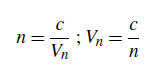
57 refractive indexDimensionless ratio, noted n, of the speed of light c in a vacuum to the velocity Vn in a transparent medium. In a transparent medium, and for the visible light range, the speed of light is always smaller than in a vacuum, so we have n ≥ 1.
The numerical value for the speed of light in a vacuum is about 300,000 km/sec. The following table gives the refractive index values for common media (according to ref. [25]; well, diamond is certainly not common, but having one of the highest refractive indices of all transparent media is mentioned for reference).
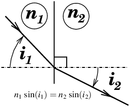
The refractive index is a fundamental constant of geometrical optics by Snell’s law (equation (15) and figure 21) :
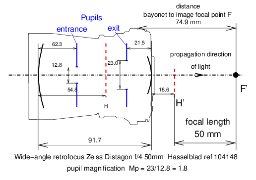
58 retro-focus lensTechnical term introduced by the French company Angénieux for a class of short focal length lenses for cine (movie) cameras, as well as a class of wide-angle lenses for mirror reflex (still) cameras in which the last lens vertex is located sufficiently ahead of the main image plane so as not to interfere with the flipping mirror in a single-lens reflex camera.
This type of lens is characterised by a pupil magnification Mp (52) greater than unity, i.e. the exit pupil diameter is greater than the entrance pupil diameter, and the pupils are quite far from the principal planes H and H′. In the case of the Zeiss Distagon lens in figure 22, the pupil magnification Mp is 1.8. 59 separation (principal points)Algebraic distance (15) HH′ between the
principal points (50) of a thick lens. Principal
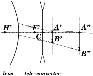
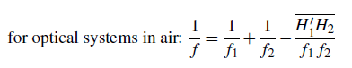
points or principal planes separation can have a positive or negative value. 60 tele-converterAn optical system, for cameras with interchangeable lenses, which is inserted between the lens and the camera body and which multiplies the transverse magnification (11) by a factor × 1.4 ; × 2 (doubler) ; × 3 … without changing the focusing plane. Tele-converters commonly used in 35 mm and medium format photography are negative optical systems (38) (figure 23). Without a tele-converter, the image is focused in A′B′. After adding the tele-converter behind the lens, A′B′ becomes a virtual object (42) of which real image (42) through the tele-converter is focused in A″ B″. In figure 23, the converter is represented by a thin negative lens for simplicity. The conversion factor is equal to the ratio of the dimensions (A″B″)/(A′B′). The thickness of the tele-converter must be equal to the distance A′A″ so that the image always focused at the same place at the rear side of the camera body. Strictly speaking, these devices should be called “magnification converters”. Indeed, if the object is at infinity, the installation of the doubler, by doubling the magnification, effectively doubles the focal length of the combined system. But if the original lens is equipped with a helical focusing ring, and focusing is done by moving the whole lens, when the doubler is installed and this ring is turned to focus on a close object, the resulting focal length (19) of the system changes as a result of the variation in the distance H′C between the lens and the converter. The focal length f of the association of two centred systems is easily calculated according to Gullstrand’s formula (equation (16) and ref. [23]) knowing the focal lengths f1 and f2 as well as the distance H′1 H2 separating the principal points (50) of the two systems :
If the distance H′1H2 (H′C
in
figure 23) between the two systems changes, the focal length
f of the combined system changes.
Do not confuse a tele-converter, which is a negative optical system (38) inserted between the lens and the camera body, with a teleside-converter (see ref.[2]), wich is an afocal optical system (2), an add-on accessory (similar to a small spotting scope) placed in front of the lens, especially for cameras with non-interchangeable lenses. 61 telephoto lensOptical formula usually of long focal length (19) relative to the diagonal of the format, in which the total mechanical lens length is shorter than the focal length; therefore the image principal point H′ (50, 49) is located in the air, in front of the first lens vertex (see figure 24).
62 transverse magnificationSee: conjugate (paraxial formulae) (11, equation (4), figure 2). References
See other articles on https://www.galerie-photo.com
Questions or comments?
Emmanuel Bigler and Yves Colombe 27thJanuary, 2021
dernière modification de cet article : 2021
|
||||||||||||||||||||||||||||||||||||||||||||||||||||||||||||||||||||||
|
|||||||||||||||||||||||||||||||||||||||||||||||||||||||||||||||||||||||


 (2)
(2) (3)
(3)
 (6)
(6) (7)
(7) (8)
(8)
 (10)
(10)

 (14)
(14)
 (16)
(16)
