|
|
|||||||||||||||||||||||||||||||||||||||||||||||||||||||||||||||||||||||||||||||||||||||||||||||||||||||||||||||||||||||||||||||||||||||||||||||||||||||||||||||||||||||||||||||||||||||||||||||||||||||||||||||||||||||||||||||||||||||||||||||||||||||||||||||||||||||||||||||||||||||||||||||||||||||||||||||||||||||||||||||||||||||||||||||||||||||||||
the author
|
Geometrical Optics: a Formulary
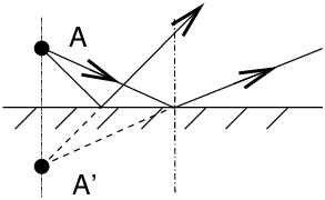
ContentsIntroductionThe practice of fully automatic cameras, of which the mobile phone may be an emblematic example in amateur photography at the beginning of the 21st century, naturally takes the photographer away from the old principles of optical image formation, and when moving to medium format or large format film cameras, and even more when starting a do-it-yourself camera construction project – e.g. a large format self-built camera, an exciting challenge – this will raise many questions to which discussion forums try to answer. Of course, it is the rule to practice medium or large format without ever using the equations and diagrams of academic courses! The purely manual, visual and tactile link of the photographer with a camera devoid of any automatism seems at a first glance incompatible with a kind of intellectual approach that would like to model everything and calculate all settings in advance... But on the other hand, the number of frequently asked technical questions on image formation, lenses, sharpness, depth of field and diffraction effects on discussion forums shows us that a quick look at good books and basic training courses in optics will never harm an artistic practice. The purpose of this formulary is therefore to encourage readers who want to go further in their practice of medium and large format cameras – practitioners of smaller film formats and digital cameras being also welcome!!!– to reread classic textbooks in geometrical or instrumental optics, and to keep this formulary handy to quickly find a formula or a diagram. I Plane MirrorsThe image A’ is symmetrical from A with respect to the mirror plane.
Successive images given by a combination of plane mirrors can be constructed geometrically
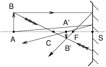
II Spherical MirrorsParaxial algebraic formulae: e.g. CS=−SC
An incident ray parallel to the axis passes through the focal point F after reflection; a ray passing through the centre C returns back to itself after reflection. CS=R SF=f=SC/2 formulae with origins at the mirror centre
C 1/CA+1/CA′=2/CS
formulae with origins at the mirror vertex
S 1/SA+1/SA′=2/SC
image magnification M = −f/FA=−FA′/f FA × FA′=f2 III Prism
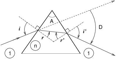
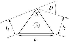
Angle of the prism A, refractive index n, deflection D, fundamental equations
A minimum of deflection exists in the symmetrical
configuration where i=i′
and r=r′.
the index of the prism is deduced from it, which allows measurements of n.
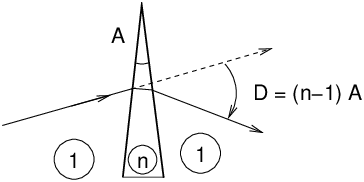
Prism with a small angle
In this case, we have the approximate relation: D=(n−1)A. Even if the prism is of low angle, and even more in the general case, a prism is only stigmatic for parallel rays at the entrance, in other words a source point at infinity. A source point at a finite distance will give a blurred image at the output. Moreover, in polychromatic lighting, the dispersion of colours further worsens the phenomenon. Dispersion: the refractive index n depends the wavelength of light λ, and therefore D depends on λ.
Taking into account that dn/dλ depends on glass properties, it follows
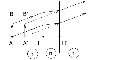
dD/dn can be calculated geometrically and is equal to b/l2. IV Plane-Parallel Plate
Example: air/glass : n=3/2 AA′ ≃ 1/3 HH′ V Spherical Refracting SurfaceLagrange-Helmholtz Formula
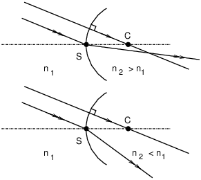
In a spherical refracting surface
Formulae with origins at the vertex S
Formulae with origins at the centre C (please note how indices 1 and 2 are swapped with respect to the other formula with origins a the vertex)
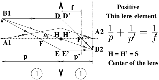
VI Thin Lens ElementsVI 1 Positive Lens ElementsDescartes’ formulae “arithmetic” (all positive quantities) for photographic lenses, or other photographic applications, projection of slides or transparencies with a real object A1 and a real image A2 read as follows
In order for the object-image conjugation to take place, it can be shown that a minimum object-image distance is required
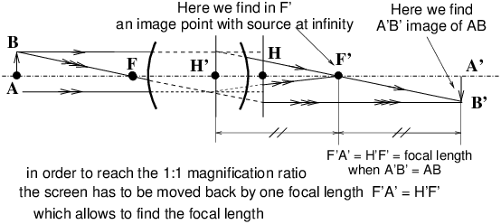
Examples: to make a projection with a positive lens of 250 mm focal length it is impossible to focus if it there is less than 1m between the object and the screen. For a 35-mm slide projector equipped with a lens of 90 mm focal length, this minimum distance is reduced to 360 mm. At the minimum distance A1 A2 = 4 f we are at a 1:1 ratio, this situation has little interest for a projection (except for image transport with image inversion in an optical instrument like old-style spyglasses), but which corresponds to the macro-photo situation with the image of the same size as the object. Shooting in this configuration called "2f-2f" corresponds to the 1:1 ratio (image size = object size) which allows to photograph a full-frame postage stamp in 35-mm format. Starting from a camera set-up for conventional landscape photography at large distances, object to infinity, image in the focal plane, in order to reach the 1:1 ratio, it will be necessary to extend the lens-to-film distance by an amount equal to one focal length, using one or more extension rings or a macro bellows (see below "Measurement of focal lengths"). VI 2 General Algebraic FormulaeFor any centred system, within the Gauss approximation.
Generalised Descartes formulae with origins at the principal planes H and H′; if it is necessary to remember only one algebraic formula, valid in all cases (real or virtual objects, positive or negative lenses, association of thin or thick lens elements), prefer this one
where C denotes the convergence of the system, with
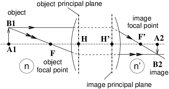
Principal points H and H′ are points on the optical axis located in the principal planes. Principal planes are object/image conjugated planes with a magnification equal to +1. Principal planes are found by looking for the intersection of an incident light ray parallel to the optical axis with the corresponding emerging ray (this determines the image principal plane passing through H′), or by finding the intersection of an emerging parallel ray with the corresponding incident ray (this determines the object principal plane passing through H). Object / image lateral magnification
Generalised Newton’s formulae
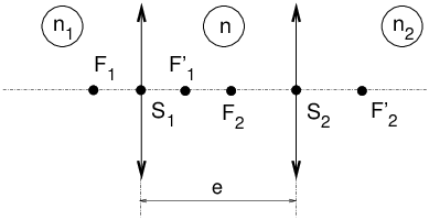
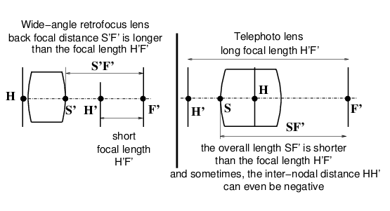
Nodal points N and N′: nodal points of a thick compound optical system are two points on the optical axis, conjugate of each other, and for which corresponding rays cross the axis at those points with the same angle w/respect to the axis (the angular ratio is equal to +1). In optical systems where refractive indices are the same on input and output, e.g. for any usual photographic application in air, nodal points are identical to principal points, i.e. N=H and N′=H′. In such a system, the most common ones in photography, the object focal length and the image focal length are equal in magnitude and of opposite sign i.e.: HF = −H′F′. Any system with identical refractive indices on input and output has only one focal length, f′=H′F′ which is positive for a positive system (most photographic lenses) and negative for a negative system (e.g. a teleconverter, a doubler). VI 3 Combination of Two Thin Lens ElementsConsider the combination of two thin lens elements, with input and output indices n1 and n2, with an intermediate index n between the two elements.
Define as C1 and C2 the convergences, being equal to the inverse of focal lengths (object or image focal length), multiplied by the corresponding refractive index (input or output) of each thin lens element.
The convergence C of the combined system is given by Gullstrand’s formula
Note: the location of principal planes H and H′ can be anywhere and without any obvious relationship between the location of the centres of thin lens elements. Simplest case: two thin lens elements stacked one over each other without gap (e=0) ⇒ C=C1+C2. In air (n1=n2=1) this yields 1/f = 1/f1 + 1/f2 VII Measurement of Focal LengthsVII 1 Cornu’s Method
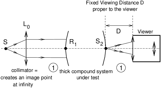
A light source S is located at the object focal point F of a positive lens L0. This set-up is named: collimator. Measurements require an optical bench and a fixed-distance viewer able to precisely focus through an eyepiece at various image locations as explained below. We assume that the optical axis is horizontal.
Now we have the location of foci F=F1, F′=F2 and the focal lengths HF1 = −H′F2 = −f′, hence we locate H and H′, at a distance of one focal length f′ from the corresponding foci. VII 2 Simplified Method to Find the Focal Length of a Thick Positive Lens
This method is valid for all positive lenses, e.g . photographic lenses. In old French textbooks, it is know as Davanne & Martin’s method (end of the XIX-st century). Note: the diagram represents H behind H′, this situation may exist for a thick compound lens.
This method is relevant to any photographic lens, providing it is a positive system (and not a tele-converter which is a negative system).
VIII Classical Visual InstrumentsVIII 1 The Human EyeIn principle a “normal” human eye sees sharp at infinity without accommodating.
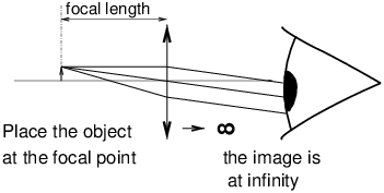
VIII 2 Loupe, Magnifying GlassThe object is located at the object focus of the magnifying glass, ⇒ the image is sent to infinity.
The intrinsic “commercial” magnification of a loupe
is frequently défined as: Mic=1/4f′,
where f′ is the focal length in meters. VIII 3 Microscope
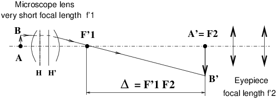
A′ B′ is the magnified image of A B. A microscope lens is a positive optical system with a large convergence (short focal length f′1, from a few mm to one cm). The eyepiece is a separate optical system of positive focal length sending the magnified image A′B′ delivered by the microscope lens to infinity for visual observation. In those conditions, the observer can see sharp without accommodating. The distance (“tube length”) F′1 F2 ~ 16 cm in classical microscopes (for biological samples). The microscope power P is defined as: P≃ Δ/f′1 f′2. The magnification Mobj. (for the microsope lens) is given by Mobj.=Δ/f′1. The intrisinc commercial magnification of the microscope Mcm is given by Mcm=Mobj.× Meyep.. The orders of magnitude are: Mcm from 25 to 2500, Mobj. from 2.5 to 120, and for eyepieces Meyep. from 5 to 20. VIII 4 Astronomical refractor telescope
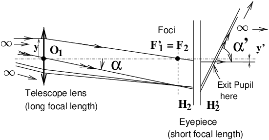
The telescope is set-up in the afocal configuration or ∞−∞ set-up, if F′1 and F2 coincidate. The angular magnification Mα is given by
In such an afocal system, the lateral magnification My is independent from the object’s position. My is given by
Typical values for Mα : f′1=1 m, f′2=2 cm ⇒ Mα=−50 (minus sign, the image is reversed). VIII 5 BinocularsA pair of binoculars is equivalent to two coupled astronomical glasses, combined with erecting prisms to restore the image "in the right direction". Meaning of commercial indications: 8 × 20 means 8 for the angular magnification (without unit) and 20 for the diameter of the lens expressed in mm. Above G ≃ 10 you don’t gain anything in terms of image details for freehand use anymore, because of the motion blur2. By dividing the diameter of the lens (e.g. 20 mm) by the magnification (e.g. 8) the diameter of the "exit pupil", i. e. the diameter of the light beam just outside the eyepiece, i.e. 2.5 mm in the selected example, is obtained. For use of the binoculars by day light, an exit pupil of 2.5 mm is sufficient. With binoculars 8 × 50, the exit pupil will be 6.25 mm which is only useful for use at night. Indeed during the day the pupil of the human eye does not exceed a diameter of about 2.5 mm; therefore this pupil size actually limits the diameter of the beam: it is useless to pay a very expensive price for a 8 × 50 instrument in this case. At night, on the other hand, since the pupil of the human eye is at least opened by 6 mm in diameter, we will benefit from a "light funnel" effect, for night scenes or star observation3. VIII 6 Appendix: Adjustment of instruments to avoid visual strainPURPOSE: to ensure that the observed image is "far ahead" and not between 1 and 20 cm... which would lead to forced accommodation, especially embarrassing when both eyes do not observe at the same distance, when the instrument is out of proper focusing. For all binocular instruments, it is essential to set the inter-pupil distance correctly, as no operator is built in the same way! Modern wide-field eyepieces make it possible to keep corrective eyeglasses on; this is important, especially for the correction of astigmatism, which can only be achieved by ophthalmic lenses. Weak myopia or hyperopia without astigmatism, on the other hand, can be easily compensated by adjusting the central sharpness setting and diopter correction of either eyepiece (see below).
————————————————————
See other articles on www.galerie-photo.com
Questions, comments?
version 4th November, 2019
|
||||||||||||||||||||||||||||||||||||||||||||||||||||||||||||||||||||||||||||||||||||||||||||||||||||||||||||||||||||||||||||||||||||||||||||||||||||||||||||||||||||||||||||||||||||||||||||||||||||||||||||||||||||||||||||||||||||||||||||||||||||||||||||||||||||||||||||||||||||||||||||||||||||||||||||||||||||||||||||||||||||||||||||||||||||||||||
|
|||||||||||||||||||||||||||||||||||||||||||||||||||||||||||||||||||||||||||||||||||||||||||||||||||||||||||||||||||||||||||||||||||||||||||||||||||||||||||||||||||||||||||||||||||||||||||||||||||||||||||||||||||||||||||||||||||||||||||||||||||||||||||||||||||||||||||||||||||||||||||||||||||||||||||||||||||||||||||||||||||||||||||||||||||||||||||

